| Geodesy |
|---|
| Fundamentals |
|---|
|
|
| Concepts |
|---|
|
|
| Technologies |
|---|
|
|
| Standards |
|---|
|
|
| History |
|---|
|
|
|
|
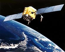
Artist's conception of GPS Block II-F satellite in Earth orbit.

U.S. Air Force Senior Airman runs through a checklist during Global Positioning System satellite operations.
The Global Positioning System (GPS) is a space-based satellite navigation system that provides location and time information in all weather conditions, anywhere on or near the Earth where there is an unobstructed line of sight to four or more GPS satellites. The system provides critical capabilities to military, civil and commercial users around the world. It is maintained by the United States government and is freely accessible to anyone with a GPS receiver.
The GPS project was developed in 1973 to overcome the limitations of previous navigation systems,
[1] integrating ideas from several predecessors, including a number of classified engineering design studies from the 1960s. GPS was created and realized by the
U.S. Department of Defense (DoD) and was originally run with 24 satellites. It became fully operational in 1994.
Roger L. Easton is generally credited as its inventor.
Advances in technology and new demands on the existing system have now led to efforts to modernize the GPS system and implement the next generation of GPS III satellites and Next Generation Operational Control System (OCX).
[2] Announcements from the Vice President and the White House in 1998 initiated these changes. In 2000, U.S. Congress authorized the modernization effort, GPS III.
History [edit]
The design of GPS is based partly on similar ground-based radio-navigation systems, such as
LORAN and the
Decca Navigator, developed in the early 1940s and used during
World War II.
Predecessors [edit]
In 1956, the German-American physicist
Friedwardt Winterberg[3] proposed a test of
general relativity (for time slowing in a strong
gravitational field) using accurate
atomic clocks placed in orbit inside artificial satellites. (To achieve accuracy requirements, GPS uses principles of general relativity to correct the satellites' atomic clocks.
[4]) Additional inspiration for GPS came when the
Soviet Union launched the first man-made satellite,
Sputnik, in 1957. Two American physicists, William Guier and George Weiffenbach, at Johns Hopkins's
Applied Physics Laboratory (APL), decided to monitor Sputnik's radio transmissions.
[5] Within hours they realized that, because of the
Doppler effect, they could pinpoint where the satellite was along its orbit. The Director of the APL gave them access to their
UNIVAC to do the heavy calculations required. The next spring, Frank McClure, the deputy director of the APL, asked Guier and Weiffenbach to investigate the inverse problem—pinpointing the user's location given that of the satellite. (The Navy was developing the submarine-launched
Polaris missile, which required them to know the submarine's location.) This led them and APL to develop the
Transit system.
[6] In 1959, ARPA (renamed
DARPA in 1972) also played a role in Transit.
[7][8][9]
 | |  |
Official logo for NAVSTAR GPS
| |
|
The first satellite navigation system,
Transit, used by the
United States Navy, was first successfully tested in 1960. It used a constellation of five satellites and could provide a navigational fix approximately once per hour. In 1967, the U.S. Navy developed the
Timationsatellite that proved the ability to place accurate clocks in space, a technology required by GPS. In the 1970s, the ground-based
Omega Navigation System, based on phase comparison of signal transmission from pairs of stations,
[10] became the first worldwide radio navigation system. Limitations of these systems drove the need for a more universal navigation solution with greater accuracy.
While there were wide needs for accurate navigation in military and civilian sectors, almost none of those was seen as justification for the billions of dollars it would cost in research, development, deployment, and operation for a constellation of navigation satellites. During the
Cold War arms race, the nuclear threat to the existence of the United States was the one need that did justify this cost in the view of the United States Congress. This deterrent effect is why GPS was funded. It is also the reason for the ultra secrecy at that time. The
nuclear triad consisted of the United States Navy's
submarine-launched ballistic missiles(SLBMs) along with
United States Air Force (USAF) strategic bombers and
intercontinental ballistic missiles (ICBMs). Considered vital to the nuclear-deterrence posture, accurate determination of the SLBM launch position was a
force multiplier.
Precise navigation would enable United States
submarines to get an accurate fix of their positions before they launched their SLBMs.
[11] The USAF, with two thirds of the nuclear triad, also had requirements for a more accurate and reliable navigation system. The Navy and Air Force were developing their own technologies in parallel to solve what was essentially the same problem. To increase the survivability of ICBMs, there was a proposal to use mobile launch platforms (such as Russian
SS-24 and
SS-25) and so the need to fix the launch position had similarity to the SLBM situation.
In 1960, the Air Force proposed a radio-navigation system called MOSAIC (MObile System for Accurate ICBM Control) that was essentially a 3-D
LORAN. A follow-on study, Project 57, was worked in 1963 and it was "in this study that the GPS concept was born". That same year, the concept was pursued as Project 621B, which had "many of the attributes that you now see in GPS"
[12] and promised increased accuracy for Air Force bombers as well as ICBMs. Updates from the Navy Transit system were too slow for the high speeds of Air Force operation. The Navy Research Laboratory continued advancements with their Timation (Time Navigation) satellites, first launched in 1967, and with the third one in 1974 carrying the first atomic clock into orbit.
[13]
Another important predecessor to GPS came from a different branch of the United States military. In 1964, the
United States Armyorbited its first Sequential Collation of Range (
SECOR) satellite used for geodetic surveying. The SECOR system included three ground-based transmitters from known locations that would send signals to the satellite transponder in orbit. A fourth ground-based station, at an undetermined position, could then use those signals to fix its location precisely. The last SECOR satellite was launched in 1969.
[14]Decades later, during the early years of GPS, civilian surveying became one of the first fields to make use of the new technology, because surveyors could reap benefits of signals from the less-than-complete GPS constellation years before it was declared operational. GPS can be thought of as an evolution of the SECOR system where the ground-based transmitters have been migrated into orbit.
Development [edit]
With these parallel developments in the 1960s, it was realized that a superior system could be developed by synthesizing the best technologies from 621B, Transit, Timation, and SECOR in a multi-service program.
During Labor Day weekend in 1973, a meeting of about 12 military officers at the Pentagon discussed the creation of a
Defense Navigation Satellite System (DNSS). It was at this meeting that "the real synthesis that became GPS was created." Later that year, the DNSS program was named
Navstar. With the individual satellites being associated with the name Navstar (as with the predecessors Transit and Timation), a more fully encompassing name was used to identify the constellation of Navstar satellites,
Navstar-GPS, which was later shortened simply to GPS.
[15]
Initially, the highest quality signal was reserved for military use, and the signal available for civilian use was intentionally degraded (
Selective Availability). This changed with President
Bill Clinton ordering Selective Availability to be turned off at midnight May 1, 2000, improving the precision of civilian GPS from 100 meters (330 ft) to 20 meters (66 ft). The executive order signed in 1996 to turn off Selective Availability in 2000 was proposed by the U.S. Secretary of Defense,
William Perry, because of the widespread growth of
differential GPS services to improve civilian accuracy and eliminate the U.S. military advantage. Moreover, the U.S. military was actively developing technologies to deny GPS service to potential adversaries on a regional basis.
[18]
Over the last decade, the U.S. has implemented several improvements to the GPS service, including new signals for civil use and increased accuracy and integrity for all users, all while maintaining compatibility with existing GPS equipment.
GPS modernization
[19] has now become an ongoing initiative to upgrade the Global Positioning System with new capabilities to meet growing military, civil, and commercial needs. The program is being implemented through a series of satellite acquisitions, including GPS Block III and the Next Generation Operational Control System (OCX). The U.S. Government continues to improve the GPS space and ground segments to increase performance and accuracy.
GPS is owned and operated by the United States Government as a national resource. Department of Defense (DoD) is the steward of GPS. Interagency GPS Executive Board (IGEB) oversaw GPS policy matters from 1996 to 2004. After that the National Space-Based Positioning, Navigation and Timing Executive Committee was established by presidential directive in 2004 to advise and coordinate federal departments and agencies on matters concerning the GPS and related systems. The executive committee is chaired jointly by the deputy secretaries of defense and transportation. Its membership includes equivalent-level officials from the departments of state, commerce, and homeland security, the joint chiefs of staff, and NASA. Components of the executive office of the president participate as observers to the executive committee, and the FCC chairman participates as a liaison.
The DoD is required by law to "maintain a Standard Positioning Service (as defined in the federal radio navigation plan and the standard positioning service signal specification) that will be available on a continuous, worldwide basis," and "develop measures to prevent hostile use of GPS and its augmentations without unduly disrupting or degrading civilian uses."
Timeline and modernization [edit]
Summary of satellites[20]
| Block | Launch
Period | Satellite launches | Currently in orbit
and healthy |
|---|
Suc-
cess | Fail-
ure | In prep-
aration | Plan-
ned |
|---|
| I | 1978–1985 | 10 | 1 | 0 | 0 | 0 |
|---|
| II | 1989–1990 | 9 | 0 | 0 | 0 | 0 |
|---|
| IIA | 1990–1997 | 19 | 0 | 0 | 0 | 9 |
|---|
| IIR | 1997–2004 | 12 | 1 | 0 | 0 | 12 |
|---|
| IIR-M | 2005–2009 | 8 | 0 | 0 | 0 | 7 |
|---|
| IIF | From 2010 | 3 | 0 | 10 | 0 | 3 |
|---|
| IIIA | From 2014 | 0 | 0 | 0 | 12 | 0 |
|---|
| IIIB | — | 0 | 0 | 0 | 8 | 0 |
|---|
| IIIC | — | 0 | 0 | 0 | 16 | 0 |
|---|
| Total | 61 | 2 | 10 | 36 | 31 |
|---|
(Last update: October 8, 2012)
PRN 01 from Block IIR-M is unhealthy
PRN 25 from Block IIA is unhealthy
PRN 32 from Block IIA is unhealthy
PRN 27 from Block IIA is unhealthy
[21] For a more complete list, see list of GPS satellite launches |
- In 1972, the USAF Central Inertial Guidance Test Facility (Holloman AFB), conducted developmental flight tests of two prototype GPS receivers over White Sands Missile Range, using ground-based pseudo-satellites.[citation needed]
- In 1978, the first experimental Block-I GPS satellite was launched.
- In 1983, after Soviet interceptor aircraft shot down the civilian airliner KAL 007 that strayed into prohibited airspace because of navigational errors, killing all 269 people on board, U.S. President Ronald Reagan announced that GPS would be made available for civilian uses once it was completed,[22][23]although it had been previously published [in Navigation magazine] that the CA code (Coarse Acquisition code) would be available to civilian users.
- By 1985, ten more experimental Block-I satellites had been launched to validate the concept. Command & Control of these satellites had moved from Onizuka AFS, CA and turned over to the 2nd Satellite Control Squadron (2SCS) located at Falcon Air Force Station in Colorado Springs, Colorado.[24][25]
- On February 14, 1989, the first modern Block-II satellite was launched.
- The Gulf War from 1990 to 1991, was the first conflict where GPS was widely used.[26]
- In 1992, the 2nd Space Wing, which originally managed the system, was de-activated and replaced by the 50th Space Wing.
- By December 1993, GPS achieved initial operational capability (IOC), indicating a full constellation (24 satellites) was available and providing the Standard Positioning Service (SPS).[27]
- Full Operational Capability (FOC) was declared by Air Force Space Command (AFSPC) in April 1995, signifying full availability of the military's secure Precise Positioning Service (PPS).[27]
- In 1996, recognizing the importance of GPS to civilian users as well as military users, U.S. President Bill Clinton issued a policy directive[28] declaring GPS to be a dual-use system and establishing an Interagency GPS Executive Board to manage it as a national asset.
- In 1998, United States Vice President Al Gore announced plans to upgrade GPS with two new civilian signals for enhanced user accuracy and reliability, particularly with respect to aviation safety and in 2000 the United States Congress authorized the effort, referring to it as GPS III.
- On May 2, 2000 "Selective Availability" was discontinued as a result of the 1996 executive order, allowing users to receive a non-degraded signal globally.
- In 2004, the United States Government signed an agreement with the European Community establishing cooperation related to GPS and Europe's planned Galileo system.
- In 2004, United States President George W. Bush updated the national policy and replaced the executive board with the National Executive Committee for Space-Based Positioning, Navigation, and Timing.[29]
- November 2004, Qualcomm announced successful tests of assisted GPS for mobile phones.[30]
- In 2005, the first modernized GPS satellite was launched and began transmitting a second civilian signal (L2C) for enhanced user performance.
- On September 14, 2007, the aging mainframe-based Ground Segment Control System was transferred to the new Architecture Evolution Plan.[31]
- On May 19, 2009, the United States Government Accountability Office issued a report warning that some GPS satellites could fail as soon as 2010.[32]
- On May 21, 2009, the Air Force Space Command allayed fears of GPS failure saying "There's only a small risk we will not continue to exceed our performance standard."[33]
- On January 11, 2010, an update of ground control systems caused a software incompatibility with 8000 to 10000 military receivers manufactured by a division of Trimble Navigation Limited of Sunnyvale, Calif.[34]
- On February 25, 2010,[35] the U.S. Air Force awarded the contract to develop the GPS Next Generation Operational Control System (OCX) to improve accuracy and availability of GPS navigation signals, and serve as a critical part of GPS modernization.
- A GPS satellite was launched on May 28, 2010.[36] The oldest GPS satellite still in operation was launched on November 26, 1990, and became operational on December 10, 1990.[37]
- The GPS satellite, GPS IIF-2, was launched on July 16, 2011 at 06:41 GMT from Space Launch Complex 37B at the Cape Canaveral Air Force Station.[38]
- The GPS satellite, GPS IIF-3, was launched on October 4, 2012 at 12:10 GMT from Space Launch Complex 37B at the Cape Canaveral Air Force Station.[39]
Awards [edit]
Francis X. Kane (Col. USAF, ret.) was inducted into the U.S. Air Force Space and Missile Pioneers Hall of Fame at Lackland A.F.B., San Antonio, Texas, March 2, 2010 for his role in space technology development and the engineering design concept of GPS conducted as part of Project 621B.
On October 4, 2011, the
International Astronautical Federation (IAF) awarded the Global Positioning System (GPS) its 60th Anniversary Award, nominated by IAF member, the American Institute for Aeronautics and Astronautics (AIAA). The IAF Honors and Awards Committee recognized the uniqueness of the GPS program and the exemplary role it has played in building international collaboration for the benefit of humanity.
Basic concept of GPS [edit]
A GPS receiver calculates its position by precisely timing the signals sent by GPS
satellites high above the Earth. Each satellite continually transmits messages that include
- the time the message was transmitted
- satellite position at time of message transmission
The receiver uses the messages it receives to determine the transit time of each message and computes the distance to each satellite using the speed of light. Each of these distances and satellites' locations define a sphere. The receiver is on the surface of each of these spheres when the distances and the satellites' locations are correct. These distances and satellites' locations are used to compute the location of the receiver using the
navigation equations. This location is then displayed, perhaps with a moving map display or
latitude and
longitude; elevation information may be included. Many GPS units show derived information such as direction and speed, calculated from position changes.
In typical GPS operation, four or more satellites must be visible to obtain an accurate result. Four sphere surfaces typically do not intersect.
[a] Because of this, it can be said with confidence that when the navigation equations are solved to find an intersection, this solution gives the position of the receiver along with the difference between the time kept by the receiver's on-board clock and the true time-of-day, thereby eliminating the need for a very large, expensive, and power hungry clock. The very accurately computed time is used only for display or not at all in many GPS applications, which use only the location. A number of applications for GPS do make use of this cheap and highly accurate timing. These include
time transfer, traffic signal timing, and
synchronization of cell phone base stations.
Although four satellites are required for normal operation, fewer apply in special cases. If one variable is already known, a receiver can determine its position using only three satellites. For example, a ship or aircraft may have known elevation. Some GPS receivers may use additional clues or assumptions such as reusing the last known
altitude,
dead reckoning,
inertial navigation, or including information from the vehicle computer, to give a (possibly degraded) position when fewer than four satellites are visible.
[42][43][44]
Structure [edit]
The current GPS consists of three major segments. These are the space segment (SS), a control segment (CS), and a user segment (US).
[45] The U.S. Air Force develops, maintains, and operates the space and control segments. GPS satellites
broadcast signals from space, and each GPS receiver uses these signals to calculate its three-dimensional location (latitude, longitude, and altitude) and the current time.
[46]
The space segment is composed of 24 to 32 satellites in
medium Earth orbit and also includes the payload adapters to the boosters required to launch them into orbit. The control segment is composed of a master control station, an alternate master control station, and a host of dedicated and shared
ground antennas and monitor stations. The user segment is composed of hundreds of thousands of U.S. and allied military users of the secure GPS Precise Positioning Service, and tens of millions of civil, commercial, and scientific users of the Standard Positioning Service (see
GPS navigation devices).
Space segment [edit]
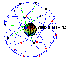
A visual example of the GPS constellation in motion with the Earth rotating. Notice how the number of satellites in view from a given point on the Earth's surface, in this example at 45°N, changes with time.
The space segment (SS) is composed of the orbiting GPS satellites, or Space Vehicles (SV) in GPS parlance. The GPS design originally called for 24 SVs, eight each in three approximately circular
orbits,
[47] but this was modified to six orbital planes with four satellites each.
[48] The orbits are centered on the Earth, not rotating with the Earth, but instead fixed with respect to the distant stars.
[49] The six orbit planes have approximately 55°
inclination (tilt relative to Earth's
equator) and are separated by 60°
right ascension of the
ascending node (angle along the equator from a reference point to the orbit's intersection).
[50] The orbital period is one-half a sidereal day, i.e., 11 hours and 58 minutes.
[51] The orbits are arranged so that at least six satellites are always within
line of sight from almost everywhere on Earth's surface.
[52] The result of this objective is that the four satellites are not evenly spaced (90 degrees) apart within each orbit. In general terms, the angular difference between satellites in each orbit is 30, 105, 120, and 105 degrees apart which sum to 360 degrees.
Orbiting at an altitude of approximately 20,200 km (12,600 mi); orbital radius of approximately 26,600 km (16,500 mi), each SV makes two complete orbits each
sidereal day, repeating the same ground track each day.
[53] This was very helpful during development because even with only four satellites, correct alignment means all four are visible from one spot for a few hours each day. For military operations, the ground track repeat can be used to ensure good coverage in combat zones.
As of December 2012,
[54] there are 32 satellites in the GPS
constellation. The additional satellites improve the precision of GPS receiver calculations by providing redundant measurements. With the increased number of satellites, the constellation was changed to a nonuniform arrangement. Such an arrangement was shown to improve reliability and availability of the system, relative to a uniform system, when multiple satellites fail.
[55]About nine satellites are visible from any point on the ground at any one time (see animation at right), ensuring considerable redundancy over the minimum four satellites needed for a position.
Control segment [edit]
The control segment is composed of
- a master control station (MCS),
- an alternate master control station,
- four dedicated ground antennas and
- six dedicated monitor stations
The MCS can also access U.S. Air Force Satellite Control Network (AFSCN) ground antennas (for additional command and control capability) and NGA (
National Geospatial-Intelligence Agency) monitor stations. The flight paths of the satellites are tracked by dedicated U.S. Air Force monitoring stations in
Hawaii,
Kwajalein,
Ascension Island,
Diego Garcia,
Colorado Springs, Colorado and
Cape Canaveral, along with shared NGA monitor stations operated in England, Argentina, Ecuador, Bahrain, Australia and Washington DC.
[56] The tracking information is sent to the Air Force Space Command MCS at
Schriever Air Force Base 25 km (16 mi) ESE of Colorado Springs, which is operated by the
2nd Space Operations Squadron (2 SOPS) of the U.S. Air Force. Then 2 SOPS contacts each GPS satellite regularly with a navigational update using dedicated or shared (AFSCN) ground antennas (GPS dedicated ground antennas are located at
Kwajalein,
Ascension Island,
Diego Garcia, and
Cape Canaveral). These updates synchronize the atomic clocks on board the satellites to within a few
nanoseconds of each other, and adjust the
ephemeris of each satellite's internal orbital model. The updates are created by a
Kalman filter that uses inputs from the ground monitoring stations,
space weather information, and various other inputs.
[57]
Satellite maneuvers are not precise by GPS standards. So to change the orbit of a satellite, the satellite must be marked unhealthy, so receivers will not use it in their calculation. Then the maneuver can be carried out, and the resulting orbit tracked from the ground. Then the new ephemeris is uploaded and the satellite marked healthy again.
The Operation Control Segment (OCS) currently serves as the control segment of record. It provides the operational capability that supports global GPS users and keeps the GPS system operational and performing within specification.
OCS successfully replaced the legacy 1970s-era mainframe computer at Schriever Air Force Base in September 2007. After installation, the system helped enable upgrades and provide a foundation for a new security architecture that supported the U.S. armed forces. OCS will continue to be the ground control system of record until the new segment, Next Generation GPS Operation Control System
[2] (OCX), is fully developed and functional.
The new capabilities provided by OCX will be the cornerstone for revolutionizing GPS's mission capabilities, and enabling
[58] Air Force Space Command to greatly enhance GPS operational services to U.S. combat forces, civil partners and myriad domestic and international users.
The GPS OCX program also will reduce cost, schedule and technical risk. It is designed to provide 50%
[59] sustainment cost savings through efficient software architecture and Performance-Based Logistics. In addition, GPS OCX expected to cost millions less than the cost to upgrade OCS while providing four times the capability.
The GPS OCX program represents a critical part of GPS modernization and provides significant information assurance improvements over the current GPS OCS program.
- OCX will have the ability to control and manage GPS legacy satellites as well as the next generation of GPS III satellites, while enabling the full array of military signals.
- Built on a flexible architecture that can rapidly adapt to the changing needs of today's and future GPS users allowing immediate access to GPS data and constellations status through secure, accurate and reliable information.
- Empowers the warfighter with more secure, actionable and predictive information to enhance situational awareness.
- Enables new modernized signals (L1C, L2C, and L5) and has M-code capability, which the legacy system is unable to do.
- Provides significant information assurance improvements over the current program including detecting and preventing cyber attacks, while isolating, containing and operating during such attacks.
- Supports higher volume near real-time command and control capabilities and abilities.
On September 14, 2011,
[60] the U.S. Air Force announced the completion of GPS OCX Preliminary Design Review and confirmed that the OCX program is ready for the next phase of development.
The GPS OCX program has achieved major milestones and is on track to support the GPS IIIA launch in May 2014.
User segment [edit]

GPS receivers come in a variety of formats, from devices integrated into cars, phones, and watches, to dedicated devices such as these.
The user segment is composed of hundreds of thousands of U.S. and allied military users of the secure GPS Precise Positioning Service, and tens of millions of civil, commercial and scientific users of the Standard Positioning Service. In general, GPS receivers are composed of an antenna, tuned to the frequencies transmitted by the satellites, receiver-processors, and a highly stable clock (often a
crystal oscillator). They may also include a display for providing location and speed information to the user. A receiver is often described by its number of channels: this signifies how many satellites it can monitor simultaneously. Originally limited to four or five, this has progressively increased over the years so that, as of 2007, receivers typically have between 12 and 20 channels.
[b]

A typical
OEM GPS receiver module measuring 15×17 mm.
GPS receivers may include an input for differential corrections, using the
RTCM SC-104 format. This is typically in the form of an
RS-232 port at 4,800 bit/s speed. Data is actually sent at a much lower rate, which limits the accuracy of the signal sent using RTCM.
[citation needed] Receivers with internal DGPS receivers can outperform those using external RTCM data.
[citation needed] As of 2006, even low-cost units commonly include
Wide Area Augmentation System (WAAS) receivers.

A typical GPS receiver with integrated antenna.
Many GPS receivers can relay position data to a PC or other device using the
NMEA 0183protocol. Although this protocol is officially defined by the National Marine Electronics Association (NMEA),
[61] references to this protocol have been compiled from public records, allowing open source tools like
gpsd to read the protocol without violating
intellectual property laws.
[clarification needed] Other proprietary protocols exist as well, such as the
SiRFand
MTK protocols. Receivers can interface with other devices using methods including a serial connection,
USB, or
Bluetooth.
Applications [edit]
While originally a military project, GPS is considered a dual-use technology, meaning it has significant military and civilian applications.
GPS has become a widely deployed and useful tool for commerce, scientific uses, tracking, and surveillance. GPS's accurate time facilitates everyday activities such as banking, mobile phone operations, and even the control of power grids by allowing well synchronized hand-off switching.
[46]
Civilian [edit]

This
antenna is mounted on the roof of a hut containing a scientific experiment needing precise timing.
Many civilian applications use one or more of GPS's three basic components: absolute location, relative movement, and time transfer.
- Astronomy: Both positional and clock synchronization data is used in Astrometry andCelestial mechanics calculations. It is also used in amateur astronomy using small telescopes to professionals observatories, for example, while finding extrasolar planets.
- Cartography: Both civilian and military cartographers use GPS extensively.
- Cellular telephony: Clock synchronization enables time transfer, which is critical for synchronizing its spreading codes with other base stations to facilitate inter-cell handoff and support hybrid GPS/cellular position detection for mobile emergency calls and other applications. The first handsets with integrated GPS launched in the late 1990s. The U.S. Federal Communications Commission (FCC) mandated the feature in either the handset or in the towers (for use in triangulation) in 2002 so emergency services could locate 911 callers. Third-party software developers later gained access to GPS APIs fromNextel upon launch, followed by Sprint in 2006, and Verizon soon thereafter.
- Clock synchronization: The accuracy of GPS time signals (±10 ns)[62] is second only to the atomic clocks upon which they are based.
- Disaster relief/emergency services: Depend upon GPS for location and timing capabilities.
- Fleet Tracking: The use of GPS technology to identify, locate and maintain contact reports with one or more fleet vehicles in real-time.
- Geofencing: Vehicle tracking systems, person tracking systems, and pet trackingsystems use GPS to locate a vehicle, person, or pet. These devices are attached to the vehicle, person, or the pet collar. The application provides continuous tracking and mobile or Internet updates should the target leave a designated area.[63]
- Geotagging: Applying location coordinates to digital objects such as photographs and other documents for purposes such as creating map overlays.
- GPS Aircraft Tracking
- GPS tours: Location determines what content to display; for instance, information about an approaching point of interest.
- Navigation: Navigators value digitally precise velocity and orientation measurements.
- Phasor measurements: GPS enables highly accurate timestamping of power system measurements, making it possible to computephasors.
- Recreation: For example, geocaching, geodashing, GPS drawing and waymarking.
- Robotics: Self-navigating, autonomous robots using a GPS sensors, which calculate latitude, longitude, time, speed, and heading.
- Surveying: Surveyors use absolute locations to make maps and determine property boundaries.
- Tectonics: GPS enables direct fault motion measurement in earthquakes.
- Telematics: GPS technology integrated with computers and mobile communications technology in automotive navigation systems
Restrictions on civilian use [edit]
The U.S. Government controls the export of some civilian receivers. All GPS receivers capable of functioning above 18 kilometres (11 mi) altitude and 515 metre per second (1,001 kn) or designed, modified for use with unmanned air vehicles like e.g. ballistic or cruise missile systems are classified as
munitions (weapons) for which
State Department export licenses are required.
[64]
This rule applies even to otherwise purely civilian units that only receive the L1 frequency and the C/A (Coarse/Acquisition) code and cannot correct for Selective Availability (SA), etc.
Disabling operation above these limits exempts the receiver from classification as a munition. Vendor interpretations differ. The rule refers to operation at both the target altitude and speed, but some receivers stop operating even when stationary. This has caused problems with some amateur radio balloon launches that regularly reach 30 kilometres (19 mi).
These limits only apply to units exported from (or which have components exported from) the USA – there is a growing trade in various components, including GPS units, supplied by other countries, which are expressly sold as
ITAR-free.
Military [edit]

Attaching a GPS guidance kit to a 'dumb' bomb, March 2003.
As of 2009, military applications of GPS include:
- Navigation: GPS allows soldiers to find objectives, even in the dark or in unfamiliar territory, and to coordinate troop and supply movement. In the United States armed forces, commanders use the Commanders Digital Assistant and lower ranks use theSoldier Digital Assistant.[65][66][67][68]
- Target tracking: Various military weapons systems use GPS to track potential ground and air targets before flagging them as hostile.[citation needed] These weapon systems pass target coordinates to precision-guided munitions to allow them to engage targets accurately. Military aircraft, particularly in air-to-ground roles, use GPS to find targets (for example, gun camera video from AH-1 Cobras in Iraq show GPS co-ordinates that can be viewed with specialized software).
- Missile and projectile guidance: GPS allows accurate targeting of various military weapons including ICBMs, cruise missiles,precision-guided munitions and Artillery projectiles. Embedded GPS receivers able to withstand accelerations of 12,000 g or about 118 km/s2 have been developed for use in 155 millimetres (6.1 in) howitzers.[69]
- Search and Rescue: Downed pilots can be located faster if their position is known.
- Reconnaissance: Patrol movement can be managed more closely.
- GPS satellites carry a set of nuclear detonation detectors consisting of an optical sensor (Y-sensor), an X-ray sensor, a dosimeter, and an electromagnetic pulse (EMP) sensor (W-sensor), that form a major portion of the United States Nuclear Detonation Detection System.[70][71] However this may be dropped in the future from excess satellites added to improve tracking in urban and mountainous terrain.[72]
Communication [edit]
Main article:
GPS signals
The navigational signals transmitted by GPS satellites encode a variety of information including satellite positions, the state of the internal clocks, and the health of the network. These signals are transmitted on two separate carrier frequencies that are common to all satellites in the network. Two different encodings are used: a public encoding that enables lower resolution navigation, and an encrypted encoding used by the U.S. military.
Message format [edit]
GPS message format
| Subframes | Description |
|---|
| 1 | Satellite clock,
GPS time relationship |
| 2–3 | Ephemeris
(precise satellite orbit) |
| 4–5 | Almanac component
(satellite network synopsis,
error correction) |
Each GPS satellite continuously broadcasts a
navigation message on L1 C/A and L2 P/Y frequencies at a rate of 50 bits per second (see
bitrate). Each complete message takes 750 seconds (12 1/2 minutes) to complete. The message structure has a basic format of a 1500-bit-long frame made up of five subframes, each subframe being 300 bits (6 seconds) long. Subframes 4 and 5 are subcommutated 25 times each, so that a complete data message requires the transmission of 25 full frames. Each subframe consists of ten words, each 30 bits long. Thus, with 300 bits in a subframe times 5 subframes in a frame times 25 frames in a message, each message is 37,500 bits long. At a transmission rate of 50 bps, this gives 750 seconds to transmit an entire almanac message. Each 30-second frame begins precisely on the minute or half-minute as indicated by the atomic clock on each satellite.
[73]
The first subframe of each frame encodes the week number and the time within the week,
[74] as well as the data about the health of the satellite. The second and the third subframes contain the
ephemeris – the precise orbit for the satellite. The fourth and fifth subframes contain the
almanac, which contains coarse orbit and status information for up to 32 satellites in the constellation as well as data related to error correction. Thus, in order to obtain an accurate satellite location from this transmitted message the receiver must demodulate the message from each satellite it includes in its solution for 18 to 30 seconds. In order to collect all the transmitted almanacs the receiver must demodulate the message for 732 to 750 seconds or 12 1/2 minutes.
[75]
All satellites broadcast at the same frequencies. Signals are encoded using
code division multiple access (CDMA) allowing messages from individual satellites to be distinguished from each other based on unique encodings for each satellite (that the receiver must be aware of). Two distinct types of CDMA encodings are used: the coarse/acquisition (C/A) code, which is accessible by the general public, and the precise (P(Y)) code, which is encrypted so that only the U.S. military can access it.
[76]
The ephemeris is updated every 2 hours and is generally valid for 4 hours, with provisions for updates every 6 hours or longer in non-nominal conditions. The almanac is updated typically every 24 hours. Additionally, data for a few weeks following is uploaded in case of transmission updates that delay data upload.
[citation needed]
| Subframe # | Page # | Name | Word # | Bits | Scale | Signed |
|---|
| 1 | all | Week Number | 3 | 1–10 | 1:1 | No |
| 1 | all | CA or P On L2 | 3 | 11,12 | 1:1 | No |
| 1 | all | URA Index | 3 | 13–16 | 1:1 | No |
| 1 | all | SV_Health | 3 | 17–22 | 1:1 | No |
| 1 | all | IODC(MSB) | 3 | 23,24 | 1:1 | No |
| 1 | all | L2Pdata flag | 4 | 1 | 1:1 | No |
| 1 | all | ResW4 | 4 | 2–24 | N/A | N/A |
| 1 | all | ResW5 | 5 | 1–24 | N/A | N/A |
| 1 | all | ResW6 | 6 | 1–24 | N/A | N/A |
| 1 | all | ResW7 | 7 | 1–16 | N/A | N/A |
| 1 | all | TGD | 7 | 17–24 | 2^-31 | Yes |
| 1 | all | IODC (LSB) | 8 | 1–8 | 1:1 | No |
| 1 | all | TOC | 8 | 9–24 | 2^4 | No |
| 1 | all | AF2 | 9 | 1–8 | 2^-55 | Yes |
| 1 | all | AF1 | 9 | 9–24 | 2^-43 | Yes |
| 1 | all | AF0 | 10 | 1–22 | 2^-31 | Yes |
| Subframe # | Page # | Name | Word # | Bits | Scale | Signed |
|---|
| 2 | all | IODE | 3 | 1–8 | 1:1 | No |
| 2 | all | CRS | 3 | 9–24 | 2^-5 | Yes |
| 2 | all | Delta N | 4 | 1–16 | 2^-43 | Yes |
| 2 | all | M0 (MSB) | 4 | 17–24 | 2^-31 | Yes |
| 2 | all | M0 (LSB) | 5 | 1–24 | | |
| 2 | all | CUC | 6 | 1–16 | 2^-29 | Yes |
| 2 | all | e (MSB) | 6 | 17–24 | 2^-33 | No |
| 2 | all | e (LSB) | 7 | 1–24 | | |
| 2 | all | CUS | 8 | 1–16 | 2^-29 | Yes |
| 2 | all | root A (MSB) | 8 | 17–24 | 2^-19 | No |
| 2 | all | root A (LSB) | 9 | 1–24 | | |
| 2 | all | TOE | 10 | 1–16 | 2^4 | No |
| 2 | all | FitInt | 10 | 17 | 1:1 | No |
| 2 | all | AODO | 10 | 18–22 | 900 | No |
| Subframe # | Page # | Name | Word # | Bits | Scale | Signed |
|---|
| 3 | all | CIC | 3 | 1–16 | 2^-29 | Yes |
| 3 | all | Omega 0 (MSB) | 3 | 17–24 | 2^-31 | Yes |
| 3 | all | Omega 0 (LSB) | 4 | 1–24 | | |
| 3 | all | CIS | 5 | 1–16 | 2^-29 | Yes |
| 3 | all | i0 (MSB) | 5 | 17–24 | 2^-31 | Yes |
| 3 | all | i0 (LSB) | 6 | 1–24 | | |
| 3 | all | CRC | 7 | 1–16 | 2^-5 | Yes |
| 3 | all | Omega (MSB) | 7 | 17–24 | 2^-31 | Yes |
| 3 | all | Omega (LSB) | 8 | 1–24 | | |
| 3 | all | Omega Dot | 9 | 1–24 | 2^-43 | Yes |
| 3 | all | IODE | 10 | 1–8 | 1:1 | No |
| 3 | all | IDOT | 10 | 9–22 | 2^-43 | Yes |
Satellite frequencies [edit]
GPS frequency overview
| Band | Frequency | Description |
|---|
| L1 | 1575.42 MHz | Coarse-acquisition (C/A) and encrypted precision (P(Y)) codes, plus the L1 civilian (L1C) and military (M) codes on future Block III satellites. |
| L2 | 1227.60 MHz | P(Y) code, plus the L2C and military codes on the Block IIR-M and newer satellites. |
| L3 | 1381.05 MHz | Used for nuclear detonation (NUDET) detection. |
| L4 | 1379.913 MHz | Being studied for additional ionospheric correction.[citation needed] |
| L5 | 1176.45 MHz | Proposed for use as a civilian safety-of-life (SoL) signal. |
All satellites broadcast at the same two frequencies, 1.57542 GHz (L1 signal) and 1.2276 GHz (L2 signal). The satellite network uses a CDMA spread-spectrum technique where the low-bitrate message data is encoded with a high-rate
pseudo-random (PRN) sequence that is different for each satellite. The receiver must be aware of the PRN codes for each satellite to reconstruct the actual message data. The C/A code, for civilian use, transmits data at 1.023 million
chips per second, whereas the P code, for U.S. military use, transmits at 10.23 million chips per second. The actual internal reference of the satellites is 10.22999999543 MHz to compensate for
relativistic effects[77][78] that make observers on Earth perceive a different time reference with respect to the transmitters in orbit. The L1 carrier is modulated by both the C/A and P codes, while the L2 carrier is only modulated by the P code.
[79] The P code can be encrypted as a so-called P(Y) code that is only available to military equipment with a proper decryption key. Both the C/A and P(Y) codes impart the precise time-of-day to the user.
The L3 signal at a frequency of 1.38105 GHz is used to transmit data from the satellites to ground stations. This data is used by the United States Nuclear Detonation (NUDET) Detection System (USNDS) to detect, locate, and report nuclear detonations (NUDETs) in the Earth's atmosphere and near space.
[80] One usage is the enforcement of nuclear test ban treaties.
The L4 band at 1.379913 GHz is being studied for additional ionospheric correction.
[citation needed]
The L5 frequency band at 1.17645 GHz was added in the process of
GPS modernization. This frequency falls into an internationally protected range for aeronautical navigation, promising little or no interference under all circumstances. The first Block IIF satellite that would provide this signal is set to be launched in 2009.
[81] The L5 consists of two carrier components that are in phase quadrature with each other. Each carrier component is bi-phase shift key (BPSK) modulated by a separate bit train. "L5, the third civil GPS signal, will eventually support safety-of-life applications for aviation and provide improved availability and accuracy."
[82]
A conditional waiver has recently been granted to
LightSquared to operate a terrestrial broadband service near the L1 band. Although LightSquared had applied for a license to operate in the 1525 to 1559 band as early as 2003 and it was put out for public comment, the FCC asked LightSquared to form a study group with the GPS community to test GPS receivers and identify issue that might arise due to the larger signal power from the LightSquared terrestrial network. The GPS community had not objected to the LightSquared (formerly MSV and SkyTerra) applications until November 2010, when LightSquared applied for a modification to its Ancillary Terrestrial Component (ATC) authorization. This filing (SAT-MOD-20101118-00239) amounted to a request to run several orders of magnitude more power in the same frequency band for terrestrial base stations, essentially repurposing what was supposed to be a "quiet neighborhood" for signals from space as the equivalent of a cellular network. Testing in the first half of 2011 has demonstrated that the impact of the lower 10 MHz of spectrum is minimal to GPS devices (less than 1% of the total GPS devices are affected). The upper 10 MHz intended for use by LightSquared may have some impact on GPS devices. There is some concern that this will seriously degrade the GPS signal for many consumer uses.
[83][84] Aviation Week magazine reports that the latest testing (June 2011) confirms "significant jamming" of GPS by LightSquared's system.
[85]
Demodulation and decoding [edit]

Demodulating and Decoding GPS Satellite Signals using the Coarse/Acquisition
Gold code.
Because all of the satellite signals are modulated onto the same L1 carrier frequency, the signals must be separated after demodulation. This is done by assigning each satellite a unique binary
sequence known as a
Gold code. The signals are decoded after demodulation using addition of the Gold codes corresponding to the satellites monitored by the receiver.
[86][87]
If the almanac information has previously been acquired, the receiver picks the satellites to listen for by their PRNs, unique numbers in the range 1 through 32. If the almanac information is not in memory, the receiver enters a search mode until a lock is obtained on one of the satellites. To obtain a lock, it is necessary that there be an unobstructed line of sight from the receiver to the satellite. The receiver can then acquire the almanac and determine the satellites it should listen for. As it detects each satellite's signal, it identifies it by its distinct C/A code pattern. There can be a delay of up to 30 seconds before the first estimate of position because of the need to read the ephemeris data.
Processing of the navigation message enables the determination of the time of transmission and the satellite position at this time. For more information see
Demodulation and Decoding, Advanced.
Navigation equations [edit]
The receiver uses messages received from satellites to determine the satellite positions and time sent. The
x, y, and
z components of satellite position and the time sent are designated as [
xi, yi, zi, ti] where the subscript
i denotes the satellite and has the value 1, 2, ...,
n, where

When the time of message reception indicated by the on-board clock is

, the true reception time is

where

is receiver's clock bias (i.e., clock delay). The message's transit time is

. Assuming the message traveled at
the speed of light,

, the distance traveled is

. Knowing the distance from receiver to satellite and the satellite's position implies that the receiver is on the surface of a sphere centered at the satellite's position with
radius equal to this distance. Thus the receiver is at or near the intersection of the surfaces of the spheres if it receives signals from more than one satellite. In the ideal case of no errors, the receiver is at the intersection of the surfaces of the spheres.
The clock error or bias, b, is the amount that the receiver's clock is off. The receiver has four unknowns, the three components of GPS receiver position and the clock bias [x, y, z, b]. The equations of the sphere surfaces are given by:
![(x-x_i)^2 + (y-y_i)^2 + (z-z_i)^2 = \bigl([ \tilde{t}_\text{r} + b - t_i]c\bigr)^2, \; i=1,2,\dots,n](http://upload.wikimedia.org/math/f/e/f/fef1a233695e2b73b0fa750a14f2674d.png)
or in terms of
pseudoranges,

, as
 .
.
These equations can be solved by algebraic or numerical methods.
Bancroft's method [edit]
Bancroft's method involves an algebraic as opposed to numerical method and can be used for the case of four or more satellites.
[88][89]Bancroft's method provides one or two solutions for the four unknowns. However when there are two solutions, only one of these two solutions will be a near earth sensible solution. When there are four satellites, we use the inverse of the B matrix in section 2 of.
[89] If there are more than four satellites then we use the pseudoinverse of the B matrix since in this case the B matrix is no longer square.
Trilateration [edit]
The receiver can use
trilateration[90][91] and one dimensional numerical root finding.
[92] Satellite position and pseudorange determines a sphere centered on the satellite with radius equal to the pseudorange. Trilateration is used to estimate receiver position based on the intersection of three sphere surfaces so determined. In the usual case of two intersections of three sphere surfaces, the point nearest the surface of the sphere corresponding to the fourth satellite is chosen. Let
d denote the signed distance from the current estimate of receiver position to the sphere around the fourth satellite. The notation,
d(correction) denotes this as a function of the clock correction. The problem is to determine the correction such that
d(correction) = 0. This is the familiar problem of finding the zeroes of a one dimensional non-linear function of a scalar variable. Iterative numerical methods, such as those found in the chapter on root finding in
Numerical Recipes can solve this type of problem.
[92]
Multidimensional Newton-Raphson calculations [edit]
Alternatively, multidimensional root finding methods such as the
Newton-Raphson method can be used.
[92] The approach is to linearize around an approximate solution, say
![\ \left [x^{(k)}, y ^{(k)}, z^{(k)}, b^{(k)}\right ]](http://upload.wikimedia.org/math/0/c/3/0c32ecd639a3623f156a678593d83504.png)
from iteration
k, then solve the linear equations derived from the quadratic equations above to obtain
![\left [x^{(k+1)}, y^{(k+1)}, z^{(k+1)}, b^{(k+1)}\right ]](http://upload.wikimedia.org/math/d/c/9/dc923433baae60fc389b303745ec2eb8.png)
. Although there is no guarantee that the method always converges due to the fact that multidimensional roots cannot be bounded, when a neighborhood containing a solution is known as is usually the case for GPS, it is quite likely that a solution will be found.
[92] It has been shown
[93] that results are comparable in accuracy to those of Bancroft's method.
Additional methods for more than four satellites [edit]
When more than four satellites are available, the calculation can use the four best or more than four, considering number of channels, processing capability, and
geometric dilution of precision (GDOP). Using more than four is an over-determined system of equations with no unique solution, which must be solved by
least-squares or a similar technique.
[89] If all visible satellites are used, the results are as good as or better than using the four best. Errors can be estimated through the residuals. With each combination of four or more satellites, a GDOP factor can be calculated, based on the relative sky directions of the satellites used.
[94] As more satellites are picked up, pseudoranges from various 4-way combinations can be processed to add more estimates to the location and clock offset. The receiver then takes the weighted average of these positions and clock offsets. After the final location and time are calculated, the location is expressed in a specific coordinate system such as latitude and longitude, using the
WGS 84 geodetic datum or a country-specific system.
[95]
Error sources and analysis [edit]
GPS error analysis examines the sources of errors in GPS results and the expected size of those errors. GPS makes corrections for receiver clock errors and other effects but there are still residual errors which are not corrected. Sources of error include signal arrival time measurements, numerical calculations, atmospheric effects, ephemeris and clock data, multipath signals, and natural and artificial interference. The magnitude of the residual errors resulting from these sources is dependent on geometric dilution of precision.
Artificial errors may result from jamming devices and threaten ships and aircraft.
[96]
Accuracy enhancement and surveying [edit]
Augmentation [edit]
Integrating external information into the calculation process can materially improve accuracy. Such augmentation systems are generally named or described based on how the information arrives. Some systems transmit additional error information (such as clock drift, ephemera, or ionospheric delay), others characterize prior errors, while a third group provides additional navigational or vehicle information.
Precise monitoring [edit]
Accuracy can be improved through precise monitoring and measurement of existing GPS signals in additional or alternate ways.
The largest remaining error is usually the unpredictable delay through the
ionosphere. The spacecraft broadcast ionospheric model parameters, but errors remain. This is one reason GPS spacecraft transmit on at least two frequencies, L1 and L2. Ionospheric delay is a well-defined function of frequency and the
total electron content (TEC) along the path, so measuring the arrival time difference between the frequencies determines TEC and thus the precise ionospheric delay at each frequency.
Military receivers can decode the P(Y) code transmitted on both L1 and L2. Without decryption keys, it is still possible to use a
codeless technique to compare the P(Y) codes on L1 and L2 to gain much of the same error information. However, this technique is slow, so it is currently available only on specialized surveying equipment. In the future, additional civilian codes are expected to be transmitted on the L2 and L5 frequencies (see
GPS modernization). Then all users will be able to perform dual-frequency measurements and directly compute ionospheric delay errors.
A second form of precise monitoring is called
Carrier-Phase Enhancement (CPGPS). This corrects the error that arises because the pulse transition of the
PRN is not instantaneous, and thus the
correlation (satellite-receiver sequence matching) operation is imperfect. CPGPS uses the L1 carrier wave, which has a
period of

, which is about one-thousandth of the C/A Gold code bit period of
, to act as an additional
clock signal and resolve the uncertainty. The phase difference error in the normal GPS amounts to 2–3 metres (6.6–9.8 ft) of ambiguity. CPGPS working to within 1% of perfect transition reduces this error to 3 centimetres (1.2 in) of ambiguity. By eliminating this error source, CPGPS coupled with DGPS normally realizes between 20–30 centimetres (7.9–12 in) of absolute accuracy.
Relative Kinematic Positioning (RKP) is a third alternative for a precise GPS-based positioning system. In this approach, determination of range signal can be resolved to a precision of less than 10 centimetres (3.9 in). This is done by resolving the number of cycles that the signal is transmitted and received by the receiver by using a combination of differential GPS (DGPS) correction data, transmitting GPS signal phase information and ambiguity resolution techniques via statistical tests—possibly with processing in real-time (
real-time kinematic positioning, RTK).
Timekeeping [edit]
Leap seconds [edit]
While most clocks derive their time from
Coordinated Universal Time (UTC), the atomic clocks on the satellites are set to GPS time (GPST; see the page of
United States Naval Observatory). The difference is that GPS time is not corrected to match the rotation of the Earth, so it does not contain
leap seconds or other corrections that are periodically added to UTC. GPS time was set to match UTC in 1980, but has since diverged. The lack of corrections means that GPS time remains at a constant offset with
International Atomic Time(TAI) (TAI – GPS = 19 seconds). Periodic corrections are performed to the on-board clocks to keep them synchronized with ground clocks.
[97]
The GPS navigation message includes the difference between GPS time and UTC. As of July 2012, GPS time is 16 seconds ahead of UTC because of the leap second added to UTC June 30, 2012.
[98] Receivers subtract this offset from GPS time to calculate UTC and specific timezone values. New GPS units may not show the correct UTC time until after receiving the UTC offset message. The GPS-UTC offset field can accommodate 255 leap seconds (eight bits).
Accuracy [edit]
GPS time is theoretically accurate to about 14 nanoseconds.
[99] However, most receivers lose accuracy in the interpretation of the signals and are only accurate to 100 nanoseconds.
[100][101]
Format [edit]
As opposed to the year, month, and day format of the
Gregorian calendar, the GPS date is expressed as a week number and a seconds-into-week number. The week number is transmitted as a ten-
bit field in the C/A and P(Y) navigation messages, and so it becomes zero again every 1,024 weeks (19.6 years). GPS week zero started at 00:00:00 UTC (00:00:19 TAI) on January 6, 1980, and the week number became zero again for the first time at 23:59:47 UTC on August 21, 1999 (00:00:19 TAI on August 22, 1999). To determine the current Gregorian date, a GPS receiver must be provided with the approximate date (to within 3,584 days) to correctly translate the GPS date signal. To address this concern the modernized GPS navigation message uses a 13-bit field that only repeats every 8,192 weeks (157 years), thus lasting until the year 2137 (157 years after GPS week zero).
Carrier phase tracking (surveying) [edit]
Another method that is used in surveying applications is carrier phase tracking. The period of the carrier frequency multiplied by the speed of light gives the wavelength, which is about 0.19 meters for the L1 carrier. Accuracy within 1% of wavelength in detecting the leading edge reduces this component of pseudorange error to as little as 2 millimeters. This compares to 3 meters for the C/A code and 0.3 meters for the P code.
However, 2 millimeter accuracy requires measuring the total phase—the number of waves multiplied by the wavelength plus the fractional wavelength, which requires specially equipped receivers. This method has many surveying applications.
Triple differencing followed by numerical root finding, and a mathematical technique called
least squares can estimate the position of one receiver given the position of another. First, compute the difference between satellites, then between receivers, and finally between epochs. Other orders of taking differences are equally valid. Detailed discussion of the errors is omitted.
The satellite carrier total phase can be measured with ambiguity as to the number of cycles. Let

denote the phase of the carrier of satellite
j measured by receiver
i at time

. This notation shows the meaning of the subscripts
i, j, and
k. The receiver (
r), satellite (
s), and time (
t) come in alphabetical order as arguments of

and to balance readability and conciseness, let

be a concise abbreviation. Also we define three functions, :

, which return differences between receivers, satellites, and time points, respectively. Each function has variables with three subscripts as its arguments. These three functions are defined below. If

is a function of the three integer arguments,
i, j, and
k then it is a valid argument for the functions, :
, with the values defined as
 ,
, , and
, and .
.
Also if
are valid arguments for the three functions and
a and
b are constants then
is a valid argument with values defined as
 ,
, , and
, and .
.
Receiver clock errors can be approximately eliminated by differencing the phases measured from satellite 1 with that from satellite 2 at the same epoch.
[102] This difference is designated as
Double differencing
[103] computes the difference of receiver 1's satellite difference from that of receiver 2. This approximately eliminates satellite clock errors. This double difference is:

Triple differencing
[104] subtracts the receiver difference from time 1 from that of time 2. This eliminates the ambiguity associated with the integral number of wavelengths in carrier phase provided this ambiguity does not change with time. Thus the triple difference result eliminates practically all clock bias errors and the integer ambiguity. Atmospheric delay and satellite ephemeris errors have been significantly reduced. This triple difference is:
Triple difference results can be used to estimate unknown variables. For example if the position of receiver 1 is known but the position of receiver 2 unknown, it may be possible to estimate the position of receiver 2 using numerical root finding and least squares. Triple difference results for three independent time pairs quite possibly will be sufficient to solve for receiver 2's three position components. This may require the use of a numerical procedure.
[105][106] An approximation of receiver 2's position is required to use such a numerical method. This initial value can probably be provided from the navigation message and the intersection of sphere surfaces. Such a reasonable estimate can be key to successful multidimensional root finding. Iterating from three time pairs and a fairly good initial value produces one observed triple difference result for receiver 2's position. Processing additional time pairs can improve accuracy, overdetermining the answer with multiple solutions. Least squares can estimate an overdetermined system. Least squares determines the position of receiver 2 which best fits the observed triple difference results for receiver 2 positions under the criterion of minimizing the sum of the squares.
Regulatory spectrum issues concerning GPS receivers [edit]
In the United States, GPS receivers are regulated under the
Federal Communications Commission's (FCC)
Part 15 rules. As indicated in the manuals of GPS-enabled devices sold in the United States, as a Part 15 device, it "must accept any interference received, including interference that may cause undesired operation."
[107] With respect to GPS devices in particular, the FCC states that GPS receiver manufacturers, "must use receivers that reasonably discriminate against reception of signals outside their allocated spectrum."
[108]
The spectrum allocated for GPS L1 use by the FCC is 1559 to 1610 MHz.
[109] Since 1996, the FCC has authorized licensed use of the spectrum neighboring the GPS band of 1525 to 1559 MHz to the
Virginia company
LightSquared. On March 1, 2001, the FCC received an application from LightSquared's predecessor,
Motient Services to use their allocated frequencies for an integrated satellite-terrestrial service.
[110] In 2002, the U.S. GPS Industry Council came to an out-of-band-emissions (OOBE) agreement with LightSquared to prevent transmissions from LightSquared's ground-based stations from emitting transmissions into the neighboring GPS band of 1559 to 1610 MHz.
[111] In 2004, the FCC adopted the OOBE agreement in its authorization for LightSquared to deploy a ground-based network that used its allocated frequencies of 1525 to 1559 MHz.
[112] This authorization was reviewed and approved by the U.S. Interdepartment Radio Advisory Committee, which includes the
U.S. Department of Agriculture,
U.S. Air Force,
U.S. Army,
U.S. Coast Guard,
Federal Aviation Administration,
National Aeronautics and Space Administration,
Interior, and
U.S. Department of Transportation.
[113]
In January 2011, the FCC conditionally authorized LightSquared's wholesale customers, such as
Best Buy,
Sharp, and
C Spire, to be able to only purchase an integrated satellite-ground-based service from LightSquared and re-sell that integrated service on devices that are equipped to only use the ground-based signal using LightSquared's allocated frequencies of 1525 to 1559 MHz.
[114] In December 2010, GPS receiver manufacturers expressed concerns to the FCC that LightSquared's signal would interfere with GPS receiver devices
[115] although the FCC's policy considerations leading up to the January 2011 order did not pertain to any proposed changes to the maximum number of ground-based LightSquared stations or the maximum power at which these stations could operate. The January 2011 order makes final authorization contingent upon studies of GPS interference issues carried out by a LightSquared led working group along with GPS industry and Federal agency participation.
GPS receiver manufacturers design GPS receivers to use spectrum beyond the GPS-allocated band. In some cases, GPS receivers are designed to use up to 400 MHz of spectrum in either direction of the L1 frequency of 1575.42 MHz.
[116] However, as regulated under the FCC's Part 15 rules, GPS receivers are not warranted protection from signals outside GPS-allocated spectrum.
[108]
The FCC adopted rules in February 2003 that allowed Mobile Satellite Service (MSS) licensees such as LightSquared to construct ground-based towers in their licensed spectrum to "promote more efficient use of terrestrial wireless spectrum."
[117] In July 2010, the FCC stated that it expected LightSquared to use its authority to offer an integrated satellite-terrestrial service to "provide mobile broadband services similar to those provided by terrestrial mobile providers and enhance competition in the mobile broadband sector."
[118] However, GPS receiver manufacturers have argued that LightSquared's licensed spectrum of 1525 to 1559 MHz was never envisioned as being used for high-speed wireless broadband although there is no regulatory or legal backing of this claim.
[119] To build public support of efforts to reverse the 2004 FCC authorization of LightSquared's network, GPS receiver manufacturer
Trimble Navigation Ltd. formed the "Coalition To Save Our GPS."
[120]
Other systems [edit]
Other satellite navigation systems in use or various states of development include:
- GLONASS – Russia's global navigation system. Fully operational worldwide.
- Galileo – a global system being developed by the European Union and other partner countries, planned to be operational by 2014 (and fully deployed by 2019)
- Beidou – People's Republic of China's regional system, currently limited to Asia and the West Pacific[126]
- COMPASS – People's Republic of China's global system, planned to be operational by 2020[127][128]
- IRNSS – India's regional navigation system, planned to be operational by 2014, covering India and Northern Indian Ocean[129]
- QZSS – Japanese regional system covering Asia and Oceania


_bombs_in_the_forward_mess_decks.jpg)

